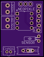
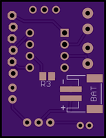
Tonight I got some real headway on my small LED driver. I added the ability to change the number of NeoPixels that are displayed, then update the onboard flash memory so that the ATtiny remembers what you selected even after a power cycle.
So now if you press and hold either of the two buttons, then turn the board on, it will let you select the number of LEDs to use. Just press the Color or Mode buttons to add or remove an LED address.
Q: why would I want to change the number of LEDs that I am using on the fly?
A: Basically, the LEDiva™ is intended to be a generic all purpose NeoPixel driver. You could use 140 NeoPixels, or just one. Some of the animations, like colorWipe();, start with the first LED address and loop until it gets to the last LED, as defined by the number of Pixels the NeoPixel library was told are available on startup. There is no way for the LEDs to tell the micro controller how many of them you just connected. So the animations will just run all the way out to 140 LEDs be damned. This can slow things as down if you are only using 3 physical LED. To fix this I simply tell the NeoPixel library that I want to use all 140, but make it so that the loop that updates the LEDs stops when it reaches the user defined number of LEDs.
So if you use the new sequence to tell the LEDiva™ that you want to use 3 LEDs, it will only loop LED updates 3 time rather than 140. Now that I have added storage to the EEPROM, it will remember the number of LEDs you selected the next time you turn it on. Are it and forget it.
Here is the latest code I have:
//Color and Pattern Mode selector for NeoPixels
//Uses C_BUTTON to cycle through 9 colors and P_BUTTON to select any of the 8 pattern sequences.
// 64 total options are available
//code by Richard Albritton

#include <Adafruit_NeoPixel.h>
#include <avr/power.h>
#include <EEPROM.h>

// Interrupt Code start
#ifndef cbi
#define cbi(sfr, bit) (_SFR_BYTE(sfr) &= ~_BV(bit))
#endif
#ifndef sbi
#define sbi(sfr, bit) (_SFR_BYTE(sfr) |= _BV(bit))
#endif
// Interrupt Code end

#define PIN 0
#define Sensor 1
#define C_BUTTON 4
#define P_BUTTON 3
#define Pixels 60

Adafruit_NeoPixel strip = Adafruit_NeoPixel(Pixels, PIN, NEO_GRB + NEO_KHZ800);

int C_MODE = 1; // Current color mode.
int P_MODE = 5; // Current pattern mode.
int Cn = 9; //The number of Color options.
int Pn = 10; //The number of Pattern options.
int STrigger = 0; // This tells us if the sensor interrupt was triggered.
int LEDs = 5;
int R;
int G;
int B;
long randNumber;
int wait = 10;

void setup(){
     // This is for Trinket 5V 16MHz, you can remove these three lines if you are not using a Trinket
#if defined (__AVR_ATtiny85__)
  if (F_CPU == 16000000) clock_prescale_set(clock_div_1);
#endif
  // End of trinket special code

  pinMode(C_BUTTON, INPUT_PULLUP);
  pinMode(P_BUTTON, INPUT_PULLUP);
  strip.begin();
  strip.show(); // Initialize all pixels to 'off'
  if (!digitalRead(C_BUTTON)||!digitalRead(P_BUTTON)){
    colorChange(strip.Color(50, 50, 50));
    delay(500);
    LESsetup(1);
  }
  if(EEPROM.read(0)>0){
    LEDs = EEPROM.read(0);
  }
  pinMode(Sensor,INPUT); // Interrupt Code
  sbi(GIMSK,PCIE); // Turn on Pin Change interrupt
  sbi(PCMSK,PCINT1); // Which pins are affected by the interrupt

    colorMode(C_MODE);
  colorChange(strip.Color(R, G, B));
}

void loop(){
// Change the line below to alter the color of the lights
// The numbers represent the Red, Green, and Blue values
// of the lights, as a value between 0(off) and 1(max brightness)
ColorSelect();
PatternSelect();
    //colorMode(C_MODE);
    patternMode(P_MODE);
    STrigger = 0;
}
void ColorSelect(){
  while (digitalRead(P_BUTTON) == LOW) {
    colorChange(strip.Color(R/4, G/4, B/4));
    while (digitalRead(C_BUTTON) == LOW) {
      delay(500);
      C_MODE += 1;
      if (C_MODE > Cn) {
        C_MODE = 1;
      }
      colorMode(C_MODE);
      colorChange(strip.Color(R/4, G/4, B/4));
    }
  }
}
void PatternSelect(){
  while(digitalRead(C_BUTTON) == LOW) {
    //colorChange(strip.Color(R/4, G/4, B/4));
    while(digitalRead(P_BUTTON) == LOW) {
      delay(500);
      P_MODE += 1;
      if (P_MODE > Pn) {
        P_MODE = 1;
      }
      patternMode(P_MODE);
    }
  }
}
// Fill the dots one after the other with a color
void colorChange(uint32_t c) {
  for(uint16_t i=0; i<LEDs; i++) {
      strip.setPixelColor(i, c);
  }
  strip.show();
}

// Fill the dots one after the other with a color
void colorWipe(uint32_t c) {
  for(uint16_t i=0; i<LEDs; i++) {
      strip.setPixelColor(i, c);
      strip.show();

      delay(50);
  }
}

// Fill the dots one after the other with a color
void Sparkle(uint32_t c) {
  for(uint16_t i=0; i<LEDs; i++) {
      strip.setPixelColor(i, c);
      strip.show();
      delay(50);
  }
}

void colorMode(uint32_t m) {
  switch (m) {
    case 1: // Red
      R = 100;
      G = 0;
      B = 0;
      break;
    case 2: // Orange
      R = 75;
      G = 25;
      B = 0;
      break;
    case 3: // Yellow
      R = 50;
      G = 50;
      B = 0;
      break;
    case 4: // Green
      R = 0;
      G = 100;
      B = 0;
      break;
    case 5: // Sky Blue
      R = 0;
      G = 50;
      B = 50;
      break;
    case 6: // Blue
      R = 0;
      G = 0;
      B = 100;
      break;
    case 7: // Violet
      R = 25;
      G = 0;
      B = 75;
      break;
    case 8: // Pink
      R = 50;
      G = 0;
      B = 50;
      break;
    case 9: // White
      R = 34;
      G = 33;
      B = 33;
      break;
  }
}
void patternMode(uint32_t p) {
  switch (p) {
case 1: // Solid bright
      colorChange(strip.Color(R, G, B));
      break;
    case 2: // Solid dim
      colorChange(strip.Color(R/2, G/2, B/2));
      break;
    case 3: // Slow strobe
      wait = 800;
      colorChange(strip.Color(R, G, B));
      delay(wait);
      colorChange(strip.Color(0, 0, 0));
      delay(wait);
      break;
    case 4: // Fast strobe
      wait = 300;
      colorChange(strip.Color(R, G, B));
      delay(wait);
      colorChange(strip.Color(0, 0, 0));
      delay(wait);
      break;
    case 5: // Pulsate
      wait = 100;
      uint16_t i;
      for(i=0; i<7; i++) {
        if (STrigger) wait = 20;
        strip.setBrightness(255-(36*i));
        colorChange(strip.Color(R, G, B));
        delay(wait);
      }
      for(i=0; i<7; i++) {
        if (STrigger) wait = 20;
        strip.setBrightness(0+(36*i));
        colorChange(strip.Color(R, G, B));
        delay(wait);
      }
      break;
    case 6: // Tracer
    for(uint16_t i=0; i<LEDs; i++) {
      strip.setPixelColor(i, strip.Color(R, G, B));
      strip.show();
            PatternSelect();
          if (P_MODE != p) break;
      delay(50);
    }
    for(uint16_t i=0; i<LEDs; i++) {
        strip.setPixelColor(i, strip.Color(0, 0, 0));
        strip.show();
              PatternSelect();
            if (P_MODE != p) break;
        delay(50);
    }

      break;
    case 7: // Sparkle
      randNumber = 300;
      for(uint16_t i=0; i<LEDs; i++) {
        if (STrigger) randNumber = 60;
        if (random(randNumber) < 50) {
          strip.setPixelColor(i, strip.Color(R, G, B));
        } else {
          strip.setPixelColor(i, strip.Color(0, 0, 0));
        }
                strip.show();
        delay(20);
      }

      break;
    case 8: // Rainbow (This will not use the selected colors)
        uint16_t j;
        for(j=0; j<256; j++) {
          for(i=0; i<LEDs; i++) {
            strip.setPixelColor(i, Wheel((i+j) & 255));
          }
          strip.show();
          PatternSelect();
          if (P_MODE != p) break;
          delay(20);
        }
      break;
  case 9: // Color Pulsate
      wait = 100;
      for(i=0; i<7; i++) {
        if (STrigger){
          C_MODE += 1;
          if (C_MODE > 10)C_MODE = 1;
          colorMode(C_MODE);
        }
        strip.setBrightness(255-(36*i));
        colorChange(strip.Color(R, G, B));
        delay(wait);
      }
      for(i=0; i<7; i++) {
        if (STrigger){
          C_MODE += 1;
          if (C_MODE > 10)C_MODE = 1;
          colorMode(C_MODE);
        }
        strip.setBrightness(0+(36*i));
        colorChange(strip.Color(R, G, B));
        delay(wait);
      }
      break;
  case 10: // red/white
      wait = 100;
      colorMode(1);
      for(i=0; i<7; i++) {
        strip.setBrightness(255-(36*i));
        colorChange(strip.Color(R, G, B));
        delay(wait);
      }
      for(i=0; i<7; i++) {
        strip.setBrightness(0+(36*i));
        colorChange(strip.Color(R, G, B));
        delay(wait);
      }
      colorMode(9);
      for(i=0; i<7; i++) {
        strip.setBrightness(255-(36*i));
        colorChange(strip.Color(R, G, B));
        delay(wait);
      }
      for(i=0; i<7; i++) {
        strip.setBrightness(0+(36*i));
        colorChange(strip.Color(R, G, B));
        delay(wait);
      }
      break;
  }
}

// Input a value 0 to 255 to get a color value.
// The colours are a transition r - g - b - back to r.
uint32_t Wheel(byte WheelPos) {
  WheelPos = 255 - WheelPos;
  if(WheelPos < 85) {
   return strip.Color(255 - WheelPos * 3, 0, WheelPos * 3);
  } else if(WheelPos < 170) {
    WheelPos -= 85;
   return strip.Color(0, WheelPos * 3, 255 - WheelPos * 3);
  } else {
   WheelPos -= 170;
   return strip.Color(WheelPos * 3, 255 - WheelPos * 3, 0);
  }
}
// Set the number of LEDs that will be used
void LESsetup(int l) {
  uint16_t t=0;
  while(l){
    t++;
    if (digitalRead(C_BUTTON) == LOW) {
        delay(250);
        LEDs += 1;
        t=0;
    }
    if (digitalRead(P_BUTTON) == LOW) {
      delay(250);
      LEDs -= 1;
      t=0;
    }
    for(uint16_t i=0; i<strip.numPixels(); i++) {
      if (i<LEDs){
        strip.setPixelColor(i, strip.Color(50, 50, 50));
      }else{
        strip.setPixelColor(i, strip.Color(0, 0, 0));
      }
    }
    strip.show();
    if (t>1000){
      EEPROM.update(0, LEDs);
      l=0;
    }
  }
}
ISR(PCINT0_vect) {
        STrigger = 1;
}
Now I just need to save the color and mode to EEPROM, but I will save that for another day 🙂




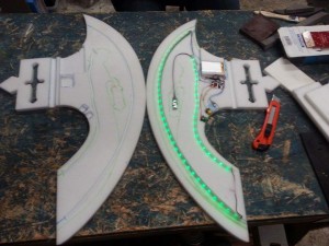 So here is a rundown of the hardware:
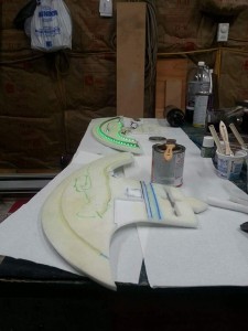 I have split the main LEDiva™ code up for this chip so that it has only a handful of game related modes along with what we are calling the Rave Mode. The main mode glows dim until the sensor detects a hit and it lights up brighter.


