Category: Hardware
Why care about MIT App Inventor?
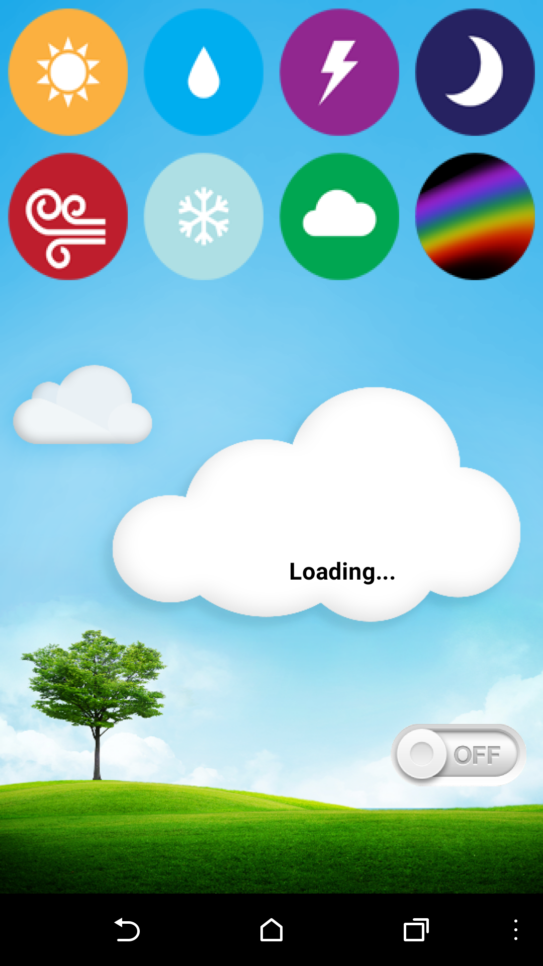
The other day I made a post about using App Inventor to create a simple UI for the Particle Photon. I have also been working on a project that involves an internet connected Weather Cloud. To make it easy for the owner to control this cloud, I have put together and Android app.
This works much faster that using something like IFTTT and requires no additional libraries like Blynk.
This brings up an interesting observation when it comes to IOT. If you want to interact with your devices, there are not a lot of good ways to go about it.
You can throw some Ajax onto your web server. If you have a web server that is.
Connect your devices API to another companies API and send your data on an epic journey when you are often in the same room as the device you are sending data to.
Make your own API and take pride that you have joined a legacy of frustrated developers world wide. Then scrap it all to use IFTTT just so much easier.
You could add a few new libraries to your firmware so that it can talk to a custom UI app like Blynk. This is actually not a bad option except that I should not have to add a new library to exploit the basic HTTP interaction protocol that comes standard with the Particle API.
Going back to the web server thing, you can just use a simple HTML page and form data for interaction. This just leaves your device credentials open for the world to see.
This is the problem with IOT right now. There are lots of ways to interact with devices, but no really good way to just go from user to device for the average person. App Inventor gives us a quick fix by letting us create an app that just uses HTTP GET and POST requests while keeping the credentials private. However, we need something better. An app that uses basic the preexisting protocol with an intuitive UI.
This is what I am working on at the moment with Vince at SoDo MakerSpace. An app like Blynk with no additional libraries, IFTTT without the additional API hooks, and Ajax without all of the coding.
I feel like this will help to open the door to the dream of IOT for the masses.
OpenCV and Python Color Detection – PyImageSearch
I am working on some stuff at the Makerspace that involves computer vision. Hopefully this information will help. Currently we are trying to do this another way, but it is just getting to be more complicated than I think it should be.
Python code for taking a photo and saving it:
Import picamera
camera = picamera.PiCamera()
camera.capture('image.png')
https://www.raspberrypi.org/documentation/usage/camera/python/README.md
Button Pressed code:
import os
import time
import RPi.GPIO as GPIO

GPIO.setmode(GPIO.BCM)
GPIO.setup(23, GPIO.IN)
GPIO.setup(18, GPIO.OUT)

def loop():
    if (GPIO.input(23) == False):
        os.system('Enter the command to execute your code')

    if Test == "open":
        GPIO.output(18, True)
    else:
        GPIO.output(18, False)
loop()
finally:
    GPIO.cleanup()
This should listen for the button to be pressed, then it will run your code. If the code returns Test as “open”, Pin 18 goes high.
The image detection part of the code. I have yet to get this going.
http://www.pyimagesearch.com/2014/08/04/opencv-python-color-detection/
Coding for the LEDiva™
Tonight I got some real headway on my small LED driver. I added the ability to change the number of NeoPixels that are displayed, then update the onboard flash memory so that the ATtiny remembers what you selected even after a power cycle.
So now if you press and hold either of the two buttons, then turn the board on, it will let you select the number of LEDs to use. Just press the Color or Mode buttons to add or remove an LED address.
Q: why would I want to change the number of LEDs that I am using on the fly?
A: Basically, the LEDiva™ is intended to be a generic all purpose NeoPixel driver. You could use 140 NeoPixels, or just one. Some of the animations, like colorWipe();, start with the first LED address and loop until it gets to the last LED, as defined by the number of Pixels the NeoPixel library was told are available on startup. There is no way for the LEDs to tell the micro controller how many of them you just connected. So the animations will just run all the way out to 140 LEDs be damned. This can slow things as down if you are only using 3 physical LED. To fix this I simply tell the NeoPixel library that I want to use all 140, but make it so that the loop that updates the LEDs stops when it reaches the user defined number of LEDs.
So if you use the new sequence to tell the LEDiva™ that you want to use 3 LEDs, it will only loop LED updates 3 time rather than 140. Now that I have added storage to the EEPROM, it will remember the number of LEDs you selected the next time you turn it on. Are it and forget it.
Here is the latest code I have:
//Color and Pattern Mode selector for NeoPixels
//Uses C_BUTTON to cycle through 9 colors and P_BUTTON to select any of the 8 pattern sequences.
// 64 total options are available
//code by Richard Albritton

#include <Adafruit_NeoPixel.h>
#include <avr/power.h>
#include <EEPROM.h>

// Interrupt Code start
#ifndef cbi
#define cbi(sfr, bit) (_SFR_BYTE(sfr) &= ~_BV(bit))
#endif
#ifndef sbi
#define sbi(sfr, bit) (_SFR_BYTE(sfr) |= _BV(bit))
#endif
// Interrupt Code end

#define PIN 0
#define Sensor 1
#define C_BUTTON 4
#define P_BUTTON 3
#define Pixels 60

Adafruit_NeoPixel strip = Adafruit_NeoPixel(Pixels, PIN, NEO_GRB + NEO_KHZ800);

int C_MODE = 1; // Current color mode.
int P_MODE = 5; // Current pattern mode.
int Cn = 9; //The number of Color options.
int Pn = 10; //The number of Pattern options.
int STrigger = 0; // This tells us if the sensor interrupt was triggered.
int LEDs = 5;
int R;
int G;
int B;
long randNumber;
int wait = 10;

void setup(){
     // This is for Trinket 5V 16MHz, you can remove these three lines if you are not using a Trinket
#if defined (__AVR_ATtiny85__)
  if (F_CPU == 16000000) clock_prescale_set(clock_div_1);
#endif
  // End of trinket special code

  pinMode(C_BUTTON, INPUT_PULLUP);
  pinMode(P_BUTTON, INPUT_PULLUP);
  strip.begin();
  strip.show(); // Initialize all pixels to 'off'
  if (!digitalRead(C_BUTTON)||!digitalRead(P_BUTTON)){
    colorChange(strip.Color(50, 50, 50));
    delay(500);
    LESsetup(1);
  }
  if(EEPROM.read(0)>0){
    LEDs = EEPROM.read(0);
  }
  pinMode(Sensor,INPUT); // Interrupt Code
  sbi(GIMSK,PCIE); // Turn on Pin Change interrupt
  sbi(PCMSK,PCINT1); // Which pins are affected by the interrupt

    colorMode(C_MODE);
  colorChange(strip.Color(R, G, B));
}

void loop(){
// Change the line below to alter the color of the lights
// The numbers represent the Red, Green, and Blue values
// of the lights, as a value between 0(off) and 1(max brightness)
ColorSelect();
PatternSelect();
    //colorMode(C_MODE);
    patternMode(P_MODE);
    STrigger = 0;
}
void ColorSelect(){
  while (digitalRead(P_BUTTON) == LOW) {
    colorChange(strip.Color(R/4, G/4, B/4));
    while (digitalRead(C_BUTTON) == LOW) {
      delay(500);
      C_MODE += 1;
      if (C_MODE > Cn) {
        C_MODE = 1;
      }
      colorMode(C_MODE);
      colorChange(strip.Color(R/4, G/4, B/4));
    }
  }
}
void PatternSelect(){
  while(digitalRead(C_BUTTON) == LOW) {
    //colorChange(strip.Color(R/4, G/4, B/4));
    while(digitalRead(P_BUTTON) == LOW) {
      delay(500);
      P_MODE += 1;
      if (P_MODE > Pn) {
        P_MODE = 1;
      }
      patternMode(P_MODE);
    }
  }
}
// Fill the dots one after the other with a color
void colorChange(uint32_t c) {
  for(uint16_t i=0; i<LEDs; i++) {
      strip.setPixelColor(i, c);
  }
  strip.show();
}

// Fill the dots one after the other with a color
void colorWipe(uint32_t c) {
  for(uint16_t i=0; i<LEDs; i++) {
      strip.setPixelColor(i, c);
      strip.show();

      delay(50);
  }
}

// Fill the dots one after the other with a color
void Sparkle(uint32_t c) {
  for(uint16_t i=0; i<LEDs; i++) {
      strip.setPixelColor(i, c);
      strip.show();
      delay(50);
  }
}

void colorMode(uint32_t m) {
  switch (m) {
    case 1: // Red
      R = 100;
      G = 0;
      B = 0;
      break;
    case 2: // Orange
      R = 75;
      G = 25;
      B = 0;
      break;
    case 3: // Yellow
      R = 50;
      G = 50;
      B = 0;
      break;
    case 4: // Green
      R = 0;
      G = 100;
      B = 0;
      break;
    case 5: // Sky Blue
      R = 0;
      G = 50;
      B = 50;
      break;
    case 6: // Blue
      R = 0;
      G = 0;
      B = 100;
      break;
    case 7: // Violet
      R = 25;
      G = 0;
      B = 75;
      break;
    case 8: // Pink
      R = 50;
      G = 0;
      B = 50;
      break;
    case 9: // White
      R = 34;
      G = 33;
      B = 33;
      break;
  }
}
void patternMode(uint32_t p) {
  switch (p) {
case 1: // Solid bright
      colorChange(strip.Color(R, G, B));
      break;
    case 2: // Solid dim
      colorChange(strip.Color(R/2, G/2, B/2));
      break;
    case 3: // Slow strobe
      wait = 800;
      colorChange(strip.Color(R, G, B));
      delay(wait);
      colorChange(strip.Color(0, 0, 0));
      delay(wait);
      break;
    case 4: // Fast strobe
      wait = 300;
      colorChange(strip.Color(R, G, B));
      delay(wait);
      colorChange(strip.Color(0, 0, 0));
      delay(wait);
      break;
    case 5: // Pulsate
      wait = 100;
      uint16_t i;
      for(i=0; i<7; i++) {
        if (STrigger) wait = 20;
        strip.setBrightness(255-(36*i));
        colorChange(strip.Color(R, G, B));
        delay(wait);
      }
      for(i=0; i<7; i++) {
        if (STrigger) wait = 20;
        strip.setBrightness(0+(36*i));
        colorChange(strip.Color(R, G, B));
        delay(wait);
      }
      break;
    case 6: // Tracer
    for(uint16_t i=0; i<LEDs; i++) {
      strip.setPixelColor(i, strip.Color(R, G, B));
      strip.show();
            PatternSelect();
          if (P_MODE != p) break;
      delay(50);
    }
    for(uint16_t i=0; i<LEDs; i++) {
        strip.setPixelColor(i, strip.Color(0, 0, 0));
        strip.show();
              PatternSelect();
            if (P_MODE != p) break;
        delay(50);
    }

      break;
    case 7: // Sparkle
      randNumber = 300;
      for(uint16_t i=0; i<LEDs; i++) {
        if (STrigger) randNumber = 60;
        if (random(randNumber) < 50) {
          strip.setPixelColor(i, strip.Color(R, G, B));
        } else {
          strip.setPixelColor(i, strip.Color(0, 0, 0));
        }
                strip.show();
        delay(20);
      }

      break;
    case 8: // Rainbow (This will not use the selected colors)
        uint16_t j;
        for(j=0; j<256; j++) {
          for(i=0; i<LEDs; i++) {
            strip.setPixelColor(i, Wheel((i+j) & 255));
          }
          strip.show();
          PatternSelect();
          if (P_MODE != p) break;
          delay(20);
        }
      break;
  case 9: // Color Pulsate
      wait = 100;
      for(i=0; i<7; i++) {
        if (STrigger){
          C_MODE += 1;
          if (C_MODE > 10)C_MODE = 1;
          colorMode(C_MODE);
        }
        strip.setBrightness(255-(36*i));
        colorChange(strip.Color(R, G, B));
        delay(wait);
      }
      for(i=0; i<7; i++) {
        if (STrigger){
          C_MODE += 1;
          if (C_MODE > 10)C_MODE = 1;
          colorMode(C_MODE);
        }
        strip.setBrightness(0+(36*i));
        colorChange(strip.Color(R, G, B));
        delay(wait);
      }
      break;
  case 10: // red/white
      wait = 100;
      colorMode(1);
      for(i=0; i<7; i++) {
        strip.setBrightness(255-(36*i));
        colorChange(strip.Color(R, G, B));
        delay(wait);
      }
      for(i=0; i<7; i++) {
        strip.setBrightness(0+(36*i));
        colorChange(strip.Color(R, G, B));
        delay(wait);
      }
      colorMode(9);
      for(i=0; i<7; i++) {
        strip.setBrightness(255-(36*i));
        colorChange(strip.Color(R, G, B));
        delay(wait);
      }
      for(i=0; i<7; i++) {
        strip.setBrightness(0+(36*i));
        colorChange(strip.Color(R, G, B));
        delay(wait);
      }
      break;
  }
}

// Input a value 0 to 255 to get a color value.
// The colours are a transition r - g - b - back to r.
uint32_t Wheel(byte WheelPos) {
  WheelPos = 255 - WheelPos;
  if(WheelPos < 85) {
   return strip.Color(255 - WheelPos * 3, 0, WheelPos * 3);
  } else if(WheelPos < 170) {
    WheelPos -= 85;
   return strip.Color(0, WheelPos * 3, 255 - WheelPos * 3);
  } else {
   WheelPos -= 170;
   return strip.Color(WheelPos * 3, 255 - WheelPos * 3, 0);
  }
}
// Set the number of LEDs that will be used
void LESsetup(int l) {
  uint16_t t=0;
  while(l){
    t++;
    if (digitalRead(C_BUTTON) == LOW) {
        delay(250);
        LEDs += 1;
        t=0;
    }
    if (digitalRead(P_BUTTON) == LOW) {
      delay(250);
      LEDs -= 1;
      t=0;
    }
    for(uint16_t i=0; i<strip.numPixels(); i++) {
      if (i<LEDs){
        strip.setPixelColor(i, strip.Color(50, 50, 50));
      }else{
        strip.setPixelColor(i, strip.Color(0, 0, 0));
      }
    }
    strip.show();
    if (t>1000){
      EEPROM.update(0, LEDs);
      l=0;
    }
  }
}
ISR(PCINT0_vect) {
        STrigger = 1;
}
Now I just need to save the color and mode to EEPROM, but I will save that for another day 🙂
LEDiva™ rev A sent to FAB
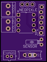
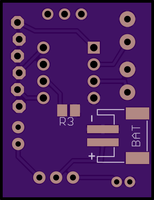
Yesterday I sent a new revision of my drop-in NeoPixel board, the LEDiva™, that included the new service mounted battery connector as well as a six pin programming connection.
This is the first step in getting the chip as small as possible. The next revision will replace the through hole version of the ATTiny 85 with a surface mounted version. After that, I will try to add a charging circuit to the board so that the battery can be charged via micro USB cable.
I do still need to work on the firmware to save data to the EPROM so it will remember the last color and pattern selected on startup. I have also thought of a way to select the number of LEDs that are being used so that the more elaborate animations look better.
The LEDiva™ is made to be used with up to 140 LEDs with unique addresses. Since I am mostly just going to sell the controller board, I do not know how many LEDs any one person will be using. So I will like have the default LED number set as 30, then create a scenario were you can use the two buttons to turn more LEDs on or off. Once you exit the LED selection mode, it will remember the number of LEDs. The sequence will likely be something like; press and hold one of the buttons on startup, then press and hold both buttons for 5 seconds to lock in the new settings.
I will do a video of me assembling the first rev A board when it comes back from OSH Park.
Another Busy day
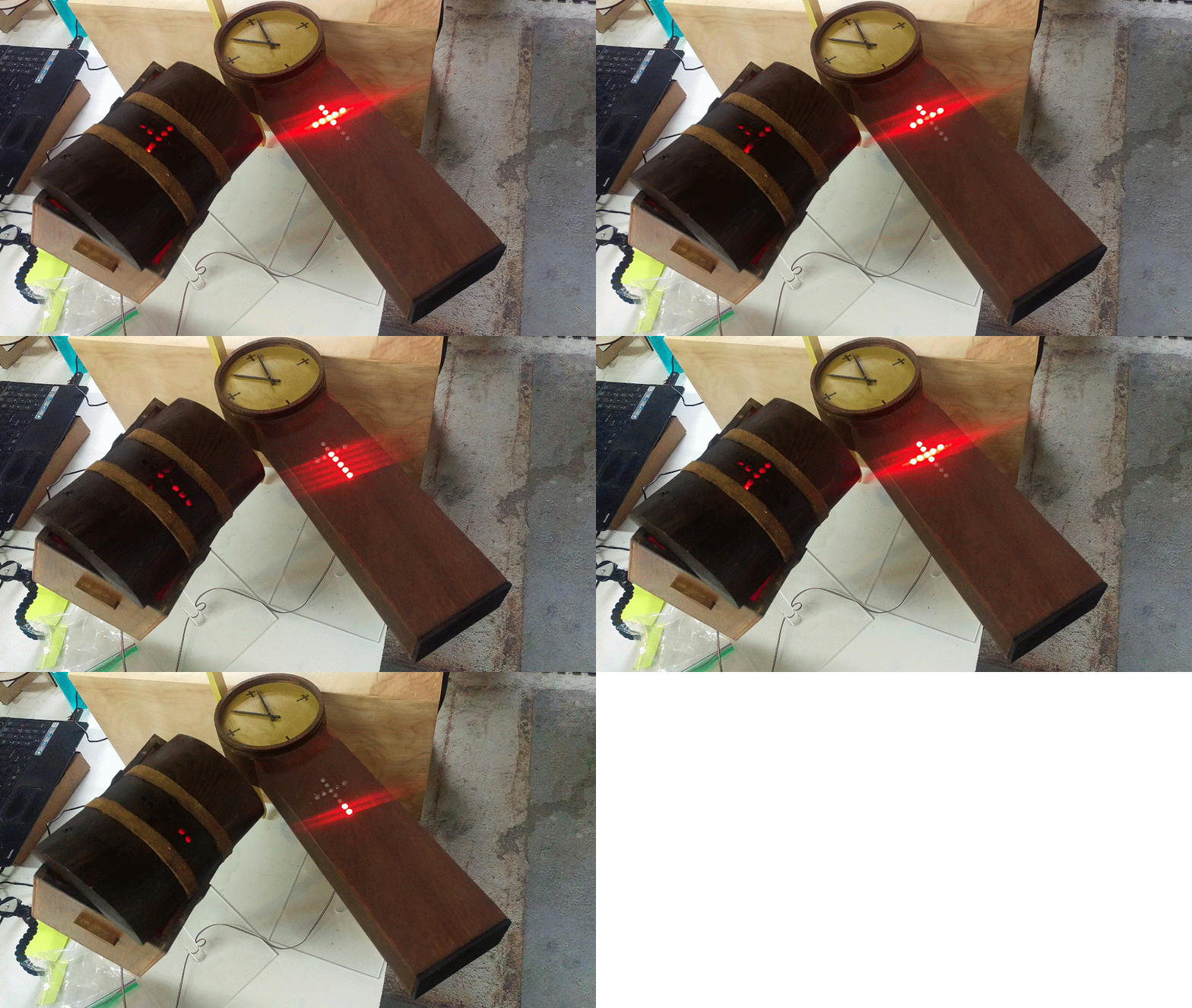
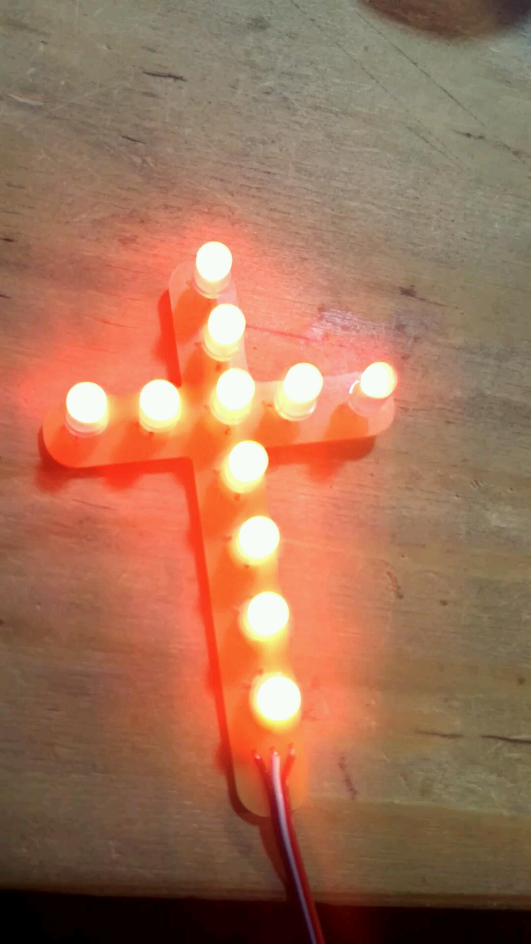
Today I am continuing the push to get stuff done for Puzzle Break as well as finishing up lighting for an artist. I have designed and milled out these crosses that will get installed into five pieces of small furniture. Originally the artist was going to just install red LEDs, but we decided to go with some WS2812B 5mm RGB LEDs.
We also have people from an arkitechture firm coming in to cut large acrylic blocks and engrave them with the laser cutter.
I am sure more will come up as well… Just another day at the office 🙂


